Standard Abutment
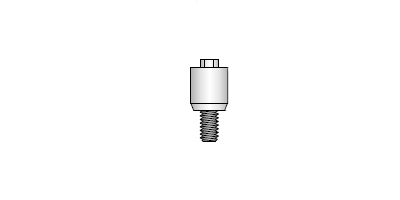
Application: For retention of prosthetic parts, this standard abutment is most commonly used. A bar-type framework is constructed on top of the standard abutment, linking the implants to one another. These ABE abutments have transcutaneous heights, L, of 4 / 5.5 / 7 and 8.5mm. Placement: The standard abutment is connected to the implant at second stage surgery upon removal of the SC4 cover screw or TBE temporary abutment. Second stage surgery is commonly done by way of an incision over the implant, reflection of the skin, securing the abutment and then suturing the skin around the abutment. An alternative method is to punch a cylinder of skin out, above the implant. This is done using the handpiece driven tissue cutter, I-TC1. The standard abutment is secured using the abutment driver, I-AD. ATorque Wrench with a bit, I-WI-A, can also be used (tighten to 20 Ncm). Prosthetic reconstruction: After abutment placement, the head of the abutment can be protected and kept clean during healing by screwing the healing cap, HB3, into the top of the abutment using a I-AD abutment driver. Arubber-based impression is taken when healing is complete by removing the healing caps and replacing them with two-part CB1 impression copings. These impression copings require an impression tray with a “window” in order for the screw of the CB1 to be accessible. When the impression material has set, the CB1 screws are loosened completely and the impression can then be withdrawn. Abutment replicas (lab analogues) are then attached to the CB1’s in the impression and the model is cast. The gold cylinder, GCP3 or GCP4, is fitted to the model and the bar is waxed up onto the gold cylinder. The gold cylinder is then loosened from the model and invested with the wax bar for the cap-on technique. An alternative is to solder a gold bar to the gold cylinder on the model.


